Voltage and current transients are a major cause of solid-state component failure in electronic systems. These transients are a result of a sudden release of stored energy. Transients may be generated from a variety of sources, both internal and external to the system. The most common causes of transients include normal switching operations of power supplies and electro- mechanical devices, AC line fluctuations, lightning surges, and electrostatic discharge (ESID).
MDE Semiconductor, Inc. offers a wide variety of silicon avalanche diodes (TVS diodes) designed to provide a high level of reliable protection against these destructive surges.
Silicon avalanche diodes are manufactured with large area junctions to provide a high surge current handling capability. They are further characterized by an extremely fast response time, and low dynamic impedance in the avalanche mode. Silicon TVS’s offer several advantages including:
- Low clamping voltages
- No wear-out limitation
- Small physical size
- Wide voltage range
- High transient power dissipation
These devices are available in a wide variety of axial lead packages and surface mount with plastic encapsulation. In applications requiring extremely high levels of transient absorption capability, MDE Semiconductor, Inc. offers a complete line of custom and standard TVS high current stacked assemblies.
No matter what the application however, certain device parameters and guidelines form the basis for selecting transient voltage suppressors.
TVS TERMINOLOGY
Certain key terms must be defined before discussing how to choose the current TVS.
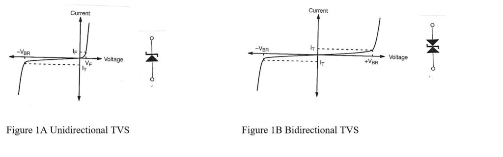
The typical V-I characteristics curve for a unidirectional transient suppressor is shown in Figure 1A. The curve shown for a bidirectional TVS, is shown in Figure 1B.
The key TVS parameters are:
- Minimum breakdown voltage (VBR) is the point where the TVS becomes a low impedance path for the transient (i.e. The device goes into avalanche breakdown).
- Test current (IT) is the current where the break down voltage is
- Reverse stand-off voltage (VRWM) is the maxi mum rated DC operating voltage. At this level, the TVS will be in a non-conducting mode. This parameter is also referred to as working voltage.
- Maximum reverse leakage current (lR) is the maxi mum current measured at the working
- Maximum peak pulse current (IPP) is the maximum permissible surge current for the
- Maximum clamping voltage (Vc) is the maximum voltage drop across the TVS while it is subjected to the maximum peak pulse current. This is the maximum voltage that the circuit will be exposed to. The clamping voltage is approximately 3xVBR.
POWER RATING AND SURGE WAVEFORMS
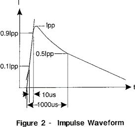
One of the most widely recognized surge waveform is the double exponential pulse shown in Figure 2. The pulse is defined by its rise time (tr)and duration (tp). Pulse time duration (tp)is defined as that point where the pulse current decays to 50% of lpp. For example, a 10 X l000µs pulse would have a l0µs rise time and would decay to 50% of the peak value in 1m
The power rating of the suppressor is the product of Vc and lpp.
Pp = Vc X lpp
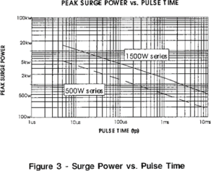
Although the 8 x 20µs and the 10 x 1000 µs pulses are used as reference for many of the TVS diodes available, the power rating of the device may be increased for shorter duration pulses as shown in Figure 3.
CHOOSING THE CORRECT TRANSIENT VOLTAGE SUPPRESSOR
The following guidelines are recommended for choosing a device that will provide optimum transient suppression in a circuit:
- Determine the maximum DC or continuous operating voltage of the circuit. Use the nominal circuit voltage and a “high side”
- Working voltage (VRWM) – Select a TVS with a reverse stand-off voltage equal to or greater than the circuit operating voltage which was determined in step
- This will ensure that the TVS will draw a negligible amount of current during normal circuit operating conditions. If the working voltage is chosen to be too low, the device may go into avalanche or may affect circuit operation by drawing too much leakage current
- Peak pulse power (Pp) – Determine the transient conditions of the circuit. Define the wave shape or transient source and the pulse duration. Choose a TVS that is capable of dissipating the expected peak pulse
- Maximum clamping voltage (Vc) – Select a TVS with a clamping voltage less than the voltage, which can cause circuit damage.
UNIDIRECTIONAL OR BIDIRECTIONAL
It is also often misunderstood that a bidirectional TVS is needed to suppress negative transient pulses. This is not the case however. A bidirectional TVS is needed in AC applications or if the data line signals swing plus and minus. Also, a bidirectional TVS is sometimes used to decrease capacitance. If the circuit only has positive signal levels, a unidirectional TVS will usually suffice.
The TVS will operate in the following manner: Under positive transient conditions, the device will avalanche and conduct in the reverse breakdown direction as expected. Under negative surge conditions, the device will conduct like a forward biased diode and still absorb the transient energy. This is NOT true however for the low capacitance devices. These are always connected in a bidirectional mode in order to protect the internal low capacitance diode from being damaged by a reverse surge.
TEMPERATURE CONSIDERATIONS
Transient voltage suppressors are designed to operate over a wide temperature range, typically -55 ‘C to +155 ‘C. If the application requires the TVS to operate at varying temperatures, the characteristics of the device must be considered at the expected temperature extremes.
- Reverse current (IR) – Reverse current increases with temperature. Consult data sheet for high temperature leakage current
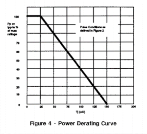
- Power dissipation – As the junction temperature of the device increases, the power dissipating capability decreases. The peak power derates linearly from +25 C to T(max). An example power derating curve is shown in Figure
- Temperature coefficient of breakdown voltage (Tcbv)- This value is given on the data sheet as a percent change in VBR per degree Celsius.