
Paralleling TVS Diodes for Higher Power Capability
Silicon Avalanche Transient Voltage Suppressors (TVS’s) offer a great deal of flexibility in circuit protection. Fortunately, these devices are available in voltages ranging from 5 through 550 volts and in power ratings up to 230 kw. In addition, they have been used in higher voltage and power combinations by taking advantage of the ability to use these TVS diodes in parallel. They may be series stacked or combined in parallel for higher ratings. (These combinations will be explored in future Briefs.)
How to Combine TVS Diodes in Parallel for Higher Ratings – The Basics
Power ratings for individual TVS devices are expressed in Watts or Kilowatts, usually based on industry standard pulse waveforms. For example, 10/1000 has a rise time to peak of 10 μsec and a decay to ½ value of 1000 μsec. They can be de-rated for other pulse waveshapes using the Pulse vs Time Curves (usually provided with the data sheets), since the usual requirement is that matching in terms of clamping diode voltage is necessary in order to share pulse current equally.
Current Sharing
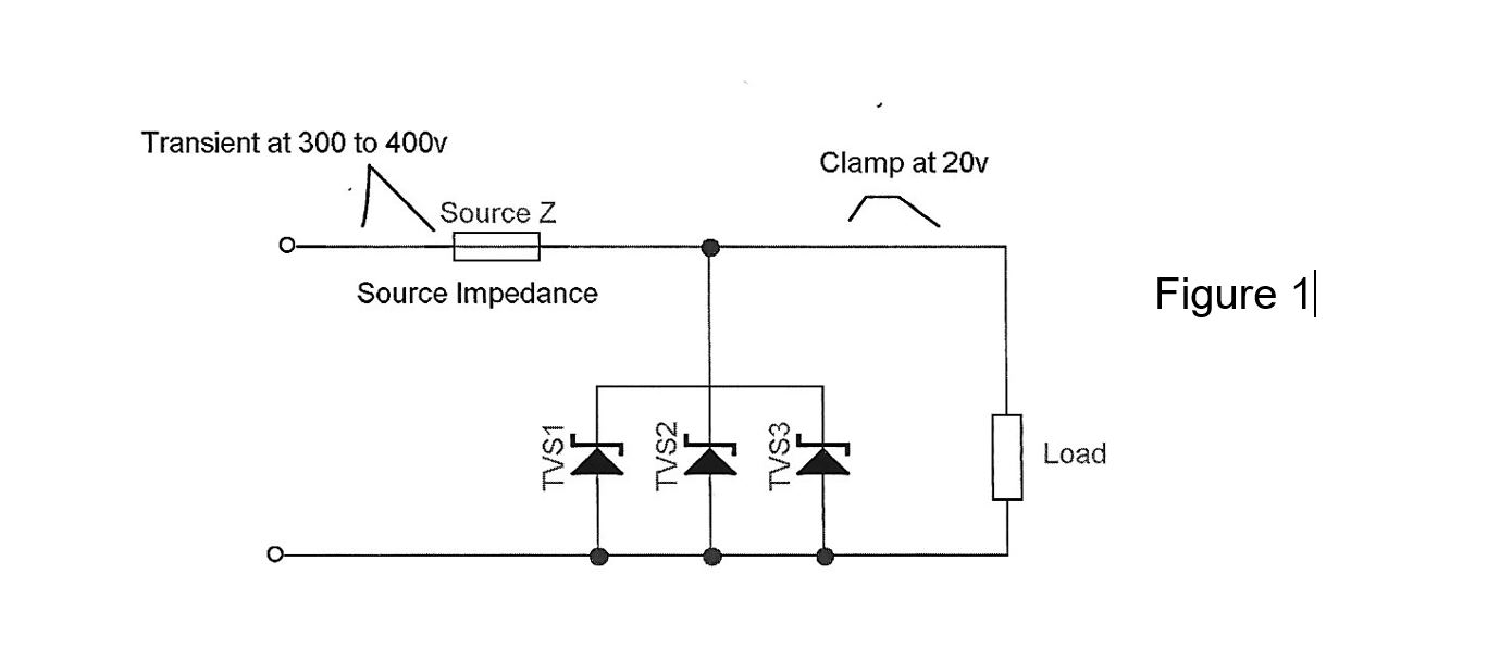
This is demonstrated in Figure 1, where we have a 300V transient of 150A. This will be divided by 3 TVS diodes in parallel (1.5KE15). Since 150A is greater than the single device capacity, which is 71.7A, the 3 will each share 1/3 of the pulse or 50A. This will then mean the load will be protected, since the voltage across the load will only be 20V.
If, however, the result of the parallel TVS diodes in parallel is too close, the upset threshold of the equipment being protected an additional TVS may be used in parallel to reduce the voltage to a safe level. This is important to keep in mind, since TVS diodes in parallel do not always share current equally.
Matching
While all 3 or 4 TVS devices used in this example are of the same part number, each unit may have its own value of breakdown voltage, reverse leakage, and clamping voltage. These differences are due to minor variations in dynamic impedance within the device specifications. If close attention is not made to matching these units, the device with the lowest breakdown voltage with typically conduct first and will carry a disproportionate amount of the transient current.
So, the best method for matching is to test with a modest waveform like 8/20 at, for example, 10 amps peak. Then, measure and note the voltage. Sort and use the units grouped as sets closest in voltage.
If this is not possible, use the same part number from similar production runs in groups as required.
If matching is not possible due to lab or production limitations, just simply use the part number from the same manufacturer and possibly use an additional parallel unit to improve the reliability of the design.
With proper selection and configuration, an effective combination of TVS diodes in parallel can be achieved for almost any protection required.
*************
This Tech Brief is brought to you by MDE Semiconductor, Inc. – your source for Surge Protection products. We value your feedback to enable us to supply better products and assist our customers to easily solve their problems.