Varistor vs. TVS Diode – a tough question, for sure! Let’s dig in. A varistor is a device whose resistance varies with the voltage across its terminals, but in a non-linear relationship. A few electrical devices exhibit this behavior, but the term “varistor” is reserved for components that dissipate energy in a solid material and not in a junction.
Under normal operating conditions, a varistor acts as an open circuit with high impedance. The advantage of the non-linear relationship between resistance and voltage becomes evident in the presence of a high transient voltage. The resistance of the varistor decreases with the increased voltage and it clamps the voltage to a safe level, effectively protecting the parallel components in the circuit.
Varistor vs TVS Diode
The ability to protect sensitive circuit parts from high transient voltages is the same function a TVS diode provides. There are notable differences comparing a varistor vs TVS diode which we will be examining.
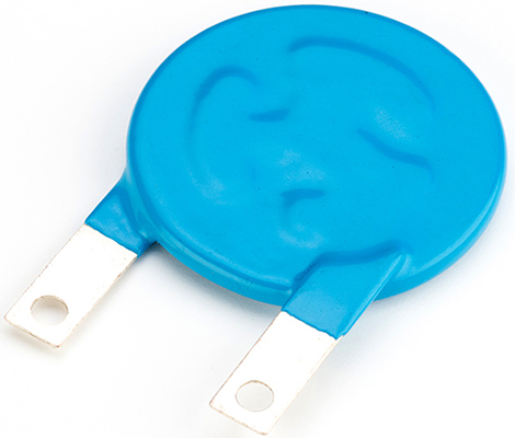
Varistors are bidirectional components suitable for both AC and DC circuits. They come in different design packages. The most popular design, the radial disc, closely resembles a capacitor but should not be confused with one.
Different types of varistors, which should you use?
These devices can be made from different types of materials. Their composition determines their electrical properties. Studying and comparing the characteristics of various formulations makes for interesting experiments and research. Commercial manufacturing companies even have created proprietary mixtures.
The current-voltage relationship of a varistor can be expressed using the following relationship:
I=KV
Where K and are constants. K is a function of the varistor’s geometry and defines the degree of nonlinearity in resistance experienced by the device. A high value of generally implies a better clamp. For an ideal resistor with a linear V-I relationship, is 1.
The most common type of varistor on the market today is the Metal Oxide Varistor, MOV.
Looking for Metal Oxide Varistors? Shop MDE Semiconductor here for our wide range of varistors, thyristors, TVS diodes
However, before MOVs were introduced, Silicon Carbide, SiC, was the varistor of choice. SiC varistors are manufactured by fusing grains of SiC together to form a ceramic base and combining additives such as graphite, various salts, and oxides to improve the properties of the final material. The drawback of these particular devices, and why MOVs have largely replaced them, is the significant amount of electric current they draw while on standby. SiC varistors have typical draw in the range 3-7.
On the other hand, MOVs have higher values compared to SiC varistors, between 20-50. During the manufacturing process, metal oxides, namely, Zinc Oxide (ZnO) are fused into a ceramic base and combined with additives such as oxides of bismuth, manganese or cobalt. A typical distribution is 90% ZnO and 10% additives. The resulting material has a polycrystalline microstructure that can dissipate large amounts of energy across its entire bulk. Next, the material is sandwiched between metal electrodes.
For the purpose of the remainder of this article, varistors will refer to MOVs.
How varistors protect circuits from high transient voltages on a microstructure level
Transient voltages are temporary voltage spikes that could occur as a result of power source fluctuations, lightning strikes, inductive load switching, electrostatic discharge, etc. The effects of these transients could range from minor to catastrophic, hence the need to protect against their occurrence.
The crystalline structure of MOVs consists of randomly oriented metal oxide grains, which are conductors separated by a resistive intergranular boundary. These boundaries exhibit P-N junction semiconductor characteristics.
In a circuit operating normally and experiencing a low voltage, only a small amount of current flows in the varistor caused by reverse leakage through the junctions. When a high transient voltage that exceeds the varistor’s breakdown voltage is applied, avalanche breakdown occurs at the junctions and the varistor becomes a conductor (The device clamps the voltage to a safe level as it conducts).
It’s important to note that these devices cannot offer protection against a continuous voltage surge, even if the magnitude of the voltage is significantly lower than the transient voltages it’s designed for. In this instance, the circuit designer must consider other options between a varistor vs TVS diode.
Specifications to know before selecting a circuit protection device
The long-term life of a varistor and its effectiveness at providing the required level of protection depends on using the device in the right circuit and following the manufacturer’s specifications.
Defined below are the typical specifications included in data sheets supplied by manufacturers. Also provided are Pulse Rating Curves or Repetitive Surge Capability Charts that paint a picture of the types of events varistors can withstand.
- Rate voltage: The maximum continuous DC or sinusoidal RMS voltage that may be applied.
- Clamping voltage: The voltage across the varistor’s terminals at which it becomes a closed circuit.
- Surge current: The maximum peak current of a given waveform for a specified pulse duration that can be applied on a varistor without it failing.
- Leakage current (standby current): The current flowing through the varistor when it is as an open-switch (non-conducting state below clamping voltage). The current is specified for a given voltage across the varistor.
- Maximum energy absorption: The maximum amount of energy the varistor can dissipate for a given pulse duration of a specified waveform
- Capacitance: Typical range between 100-1000 pF
- Response time: The time it takes the varistor to transition from a non-conducting state to conducting state after a rated voltage has been applied. That is, the duration within which the circuit is exposed to the transient voltage until the varistor clamps down on the voltage.
Procedure for selecting the best varistor for your circuit
The steps below are a quick and rough guide for choosing the best device for your design.
Looking for Metal Oxide Varistors? Shop MDE Semiconductor here for our wide range of varistors, thyristors, TVS diodes
- Understand the normal operating conditions of the circuit to determine the working voltage of the varistor
The maximum permissible operating voltage of the selected varistor should be equal to or slightly exceed the operating voltage (whether AC or DC) of the circuit. 10-15% higher is acceptable.
- Approximate the energy absorbed by the varistor during a transient event
A varistor’s energy rating is a measure of the maximum allowable energy for a specified pulse and duration of current when a continuous voltage is applied.
If the transient event is due to the discharge of an inductance (e.g., transformer), the source energy can be easily calculated. Choose a varistor with an energy absorption rating that equals or slightly exceeds the energy values associated with the event the circuit may experience. If, however, the transient voltage is due to an external event, the magnitude of the source energy is unknown. In this scenario, an approximation procedure to estimate the energy should be followed using available information at your disposal (testing, mathematical approximation, or graphical iteration).
3. Determine the peak transient current through the varistor (surge current)
If the transient is due to inductance, the peak current will not exceed the inductor current at the time of the switch. The working voltage determined in step 1 narrowed down the choice of varistors to a useful range of models. A graphical analysis can also be performed to determine the transient current from V-I characteristic curves, knowing the transient voltage and source impedance.
4. Determine the varistor’s average power dissipation requirements
The required power dissipation is the energy generated per pulse multiplied by the number of pulses per second. The selected varistor’s power rating should be equivalent or exceed this value. Recall that varistors are not power regulation devices and will not be suitable where transients occur repeatedly.
- Select a model for the required voltage-clamping characteristic
The selected varistor’s clamping voltage should approximate the highest voltage the down-line components should experience.
Varistor applications
The desirable properties of these particular devices make them useful for suppressing transients in both domestic appliances and industrial equipment. Some examples of practical uses:
- Protect telecommunication lines and equipment: Smartphones, power supply units, chargers
- Protect Industrial control equipment: Remote control systems, machine controls, alarm systems, proximity switches, LCDs
- Protect power electronics: Bridge rectifiers, electric welding, switch-mode power, high-power current converters, DC/AC converters, power semiconductors
- Protect power generating equipment: transformers, motor, and generator windings, inductors, electrical power meter
- Protect automotive electrical equipment: Engine control units, generator rectifiers, central locking systems, trip computers, wiper motors, traffic lighting, traffic signals
- Protect medical equipment: Diagnostic equipment, therapeutic equipment, power supply units
- Protect household electronics and microprocessors: Television sets, computers, washing machines controls, dimmers, lamps, thermostats, surge protection power strips
When varistors fail: their limitations
Varistors have a few limitations resulting from their construction and the way they absorb transient energy. After many large transient events, devices degrade (ceramic layer breaks down). In their degraded state, the amount of leakage current through the varistor increases leading to raised temperatures even when the circuit is operating normally. If the device is not protected, the increased heating can lead to thermal runaway.
So why would we continue to use varistors given this well-known and dangerous inevitability? The answer lies in the modern generation of varistors that have built-in thermal disconnect function. The thermal disconnect senses the increase in MOV temperature as it deteriorates. When the varistor reaches the end of its operating life, the thermal disconnect will open the circuit, protecting against fires.
Varistor vs TVS diode
Like varistors, TVS diodes are transient voltage suppression devices useful for protecting electronic components. Which one to choose depends on what response you would like to achieve in your circuit. In general, the best protection will have a fast response time, low clamping voltage, low standby current, not forgetting physical factors like failure mechanism, cost, board space, and reliability. Here’s how the two compare:
TVS diodes
- Clamp at lower voltages
- Do not degrade with time
- Have low capacitance, suited wherever signal sensitivity is a high priority e.g. USB ports
- More expensive
Varistors (MOVs)
- Clamping voltage is higher
- Degrade over time even when used within specification and become more conducting
- More effective at protecting circuits that requiring high capacitance
- Have greater tolerance for high energy/temperatures used on high voltage environments, e.g., power mains
- More cost effective
Looking for Metal Oxide Varistors? Shop MDE Semiconductor here for our wide range of varistors, thyristors, TVS diodes