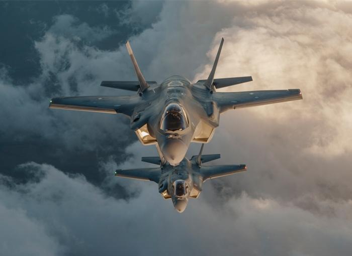
No passengers like a delayed, rerouted, or canceled flight on account of bad weather. De-icing the plane is a critical process – and not just for passenger flights. We’re proud to share that once again, MDE Semiconductor, Inc. parts have been implemented in military aircraft. We return to Lockheed Martin’s F35 Lightning II: this time in the form of clamp circuit device protecting the ice protection systems designed by Ultra Electronics.
To safeguard critical anti-icing equipment from power surges, electrostatic discharges, lightning, and short circuits during flight, Ultra Electronics turned to TVS diodes from MDE Semiconductor, Inc. In this article, we’ll put into perspective the dangers associated with icing conditions for an aircraft that is thousands of feet in the air. We’ll also discuss how our products integrate into protective clamp circuit design, as seen in the example from UE’s ice protection systems.
The Dangers of In-Flight Ice
Icing conditions occur when moisture is present and the temperature is in the freezing range, -20°C (-4°F) to +2 °C (35.6°F). In reality, water droplets in clouds can exist in a supercooled liquid state even below the freezing point, especially when there is nothing on which to freeze upon. However, as an aircraft approaches, it disturbs this intricate balance and upon impact, the droplets can now freeze.
Ice buildup on a plane’s wings, vertical and horizontal stabilizers, propellers, and tail changes the shape of these surfaces, and therefore the airflow over them. At the same time, the ice adds weight to the plane. Both conditions negatively affect the force that helps keep the plane in the air. Wind tunnel and flight tests have shown that a layer of ice no thicker than the width of coarse sandpaper can increase drag by 40% and reduce lift by 30% [1].
To compensate for these losses, a pilot would maneuver to fly at a greater angle of attack which increases fuel consumption. More importantly, degradation of the handling and control characteristics of the plane in severe conditions can cause complete loss of control.
The recommendation to pilots when faced with icing environments is to exit. Increase altitude where a plane’s performance allows, or to change direction and avoid it. Unfortunately, flying through ice is sometimes unavoidable during the critical moments of takeoff or landing as the plane might need to fly through icing activity.
Sadly, aircraft accident records have recorded fatal crashes during takeoff and landing attributed to ice buildup. For example, in 1982, a Boeing 737 crashed into the frozen Potomac River when ice accumulated on its wing during take-off from Washington DC. 78 souls perished as a result [2]. Or the 2009 Continental Express flight 3407 that crashed into a home outside Buffalo, just five miles shy of the runway. 58 people, including a man inside the house, died [3].
These and similar incidents exposed the disastrous impact of ice in-flight, justifying the need for technologies to manage or prevent its formation.

What Are Ice Protection Systems?
Depending on how ice formation is managed in flight, aircraft ice protection systems are broadly categorized into:
- De-icing systems – methods that remove ice that has formed on affected areas before it becomes dangerous.
- Anti-icing systems – methods that prevent ice from forming on the installed parts in the first place.
In the interest of safety, ice protection systems are considered as means of buying time, until a plane can safely exit those conditions. It is therefore imperative that these systems are always reliable and fully operational. MDE Semiconductor, Inc. specializes in just this sort of protective devices for critical aviation applications.
Explore datasheets and product listings here for your unique clamp circuit designs.
Examples of Ice Protection Systems
There are a variety of ice protection systems designed to cater to different categories of aircraft, and also the location on the aircraft’s frame. In general, the modes of operations of these products fall into four categories:
- Chemical application
- Breaking up formed ice
- Heating surfaces using hot air
- Heating surfaces using electrical elements
Chemical application
Chemical de-icing
To prepare for flying from an icing environment, glycol-based solutions are used to de-ice grounded planes by chemically breaking the bonds between the ice and airframe. However, the treatment has a limited period of effectiveness after which a plane would need to be de-iced again. The process itself can be time-intensive as the application is done clinically to avoid contact with critical components such as the engine, electrical receptacles, and cabin windows among other parts.
Chemical anti-icing
Some aircraft use chemicals to protect the leading edges of wings and stabilizers from ice forming. Also referred to as weeping wing systems or TKS(TM) systems, the protected edges are covered with fine wire mesh consisting of tiny holes. Once activated, anti-icing fluid (typically glycol-based) is pumped from a reservoir through the holes to depress the freezing point of the supercooled water in the cloud, and prevent freezing. Reservoir capacity is a limitation to consider when flight planning.
Breaking up formed ice
De-icing boots
These are rubber sleeves installed in the wings, horizontal and vertical stabilizer leading edges. The pneumatic leading edge boot is the most common. After activation, the boots expand when inflated with pneumatic pressure and contract through vacuum suction in cycles to break the bonds between the ice and the plane’s surface. To prevent inflated boots from affecting the airflow around the protected edges, separate installations are programmed to inflate in a sequence.
Heating surfaces using hot air
Bleed air
Hot air from the engine is compressed and directed through ducts, valves, and manifolds to the aircraft parts to be anti-iced, namely wing leading edges and slats. The process of compressing air is both energy-intensive and thermodynamically inefficient, made even more so by the transport system for the hot air. Bleed air is not a viable solution for composite materials as the high temperatures can damage them, a limitation considering that the next generation of aircraft is poised to include more composite parts.
Heating surfaces using electrical elements
Electro-thermal anti-icing
Electrically powered heaters are embedded into the interior surface requiring protection, whether metallic or composite structures to maintain sufficient temperature and prevent ice formation. Different design schemes have been conjured up by manufacturers including heated mats, internal coil wire, heated gaskets, conductive films, or tapes.
Compared to other anti-ice/de-ice systems, electro-thermal methods are a relatively new approach that requires innovation in a traditional aircraft’s design. For example, the Boeing 787 was designed to do away with the majority of pneumatic systems [4]. Instead, it features more advanced electrical components including six generators. With sufficient power available, electric heating methods which are more energy-efficient than bleed air systems were attractive.
Because today’s aircraft are dependent on complex electronics, from ice protection to navigation, these systems must be protected as electrical disturbances remain ever-present. Sensitive electronics can be protected in a clamp circuit with avalanche breakdown-style diodes that start conducting electricity once a threshold is reached to divert current away from the protected components.
Ultra Electronics’ Ice Protection Systems
With over 15 years of experience, Ultra Electronics Controls is the market leader in developing innovative Ice Protection System solutions for the Aerospace Industry. By teaming with GKN Aerospace who provided metallic or composite heater mats, the company has succeeded in providing a complete ice protection system capability.
Their systems are designed to operate in either an anti-icing, de-icing, or hybrid mode. They also cater to a range of ice protection requirements, whether simple, time/voltage, on-off control or complex multi-zone, closed-loop feedback control.
To maximize performance, UE’s system relies upon intelligent software to optimize the usage of aircraft power. In addition, for a highly controllable system, power switching may be centralized or located remotely depending on the application.
The company’s ice protection systems have been successfully implemented in the Boeing 787 Dreamliner Wing Leading Edge and Lockheed Martin’s F35 Lightning II Lift Fan inlet to name a few platforms.
Protecting The Ice Protector, Clamp Circuit Made Possible by MDE Semiconductor, Inc. Devices
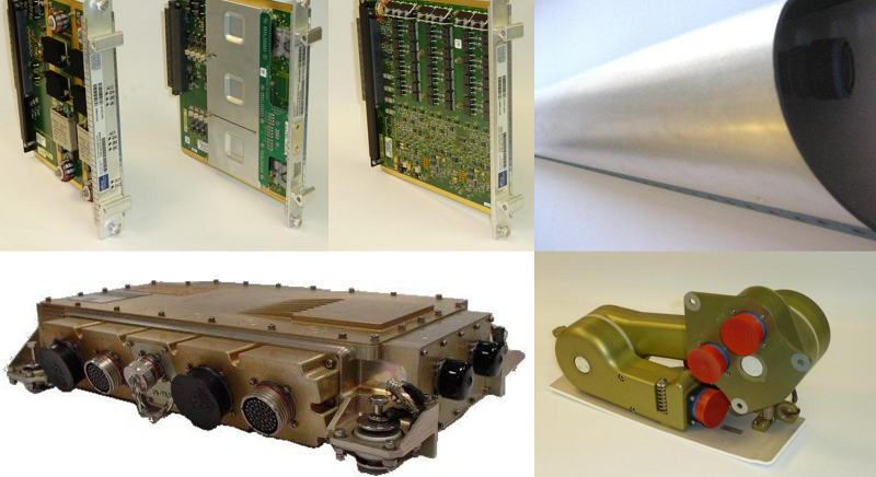
Three types of electronic circuit boards make up Ultra Electronics’ Wing Icing Protection Control Unit, WIPCU:
- The Power Supply distributes and conditions the dual 28VDC power to the other circuit boards, the Zone Controller and Sequence Controller
- The Zone Controller controls power switching to the different heater mat regions.
- The Sequence Controller maintains symmetrical ice protection by regulating the switching of the zone controllers.
Like any microprocessors connected to complex electrical and data networks, the risk of electrical transients exists. These unpredictable events can propagate from external terminals or be induced by natural occurrences such as lightning. If sufficiently energetic, these electrical anomalies can lead to failure or destruction of equipment. Given the role ice protection systems must play in the event of bad weather during flights, any such occurrences could be disastrous.
High integrity and performance were critical in the design and construction of the WIPCU which incorporates four products from our stables: MAX-100, MAX-422, 30KW60CA, and 20KP30CA. All four protective TVS diodes are bidirectional, and offer the flexibility of mounting in any position. Our products help create a clamp circuit that can withstand electrically fast transients.
The MAX-100 and MAX-422 are high current transient voltage suppressors with a surge capacity of 10KA and 8kA (8 x 20 µsec waveform) respectively. With an operating temperature ranging from -40°C to +125°C, they exhibit fast response times of less than a microsecond from 0 V to breakdown voltage.
The 30KW60CA and 20KPA30CA TVS diodes offer power and noise immunity in a tiny package and offering minimum peak pulse power ratings of 30 kW and 20kW at 10/1000 microseconds respectively. They can both operate in much harsher temperature conditions -55 to +175 °C.

The ice protection system isn’t the only part of the F35 that utilizes MDE Semiconductor, Inc. parts for protection
The 5.0MLJ12A TVS Diode is riding shotgun in the cockpit. The jet’s cockpit display got a re-design, thanks to L3 Technologies. In addition to state-of-the-art, lightweight, powerful lithium-ion batteries to act as a back-up control in an emergency power failure, the F35s are equipped with the 5.0MLJ12A surface mount TVS diode to protect the advanced electronics from power surges from lightning strikes or anomalies.
The 5.0SMLJ Series is a single TVS diode with low inductance and excellent clamping capability. They provide a working peak reverse voltage from 5V up to 170V and a 5000-watt peak pulse power. They are preferred for their fast response time: less than 1.0 ns for unidirectional devices and less than 5.0 ns for bidirectional devices from 0 V to minimum breakdown voltage. They are low-profile, designed in a flat configuration, and intended for surface mount to maximize board space.
MDE Semiconductor, Inc. offers standard and customized solutions for protected circuits to meet different requirements. A carefully selected transient voltage suppressor diode helps create a clamp circuit that can withstand electrically fast transients in your unique application. Explore datasheets and product listings here.
Sources
[1] https://www.aopa.org/-/media/files/AOPA/Home/Pilot-Resources/ASI/Safety-Advisors/sa11.pdf
[2] https://www.history.com/this-day-in-history/plane-crashes-into-potomac
[3] https://www.scientificamerican.com/article/ice-flight-3407